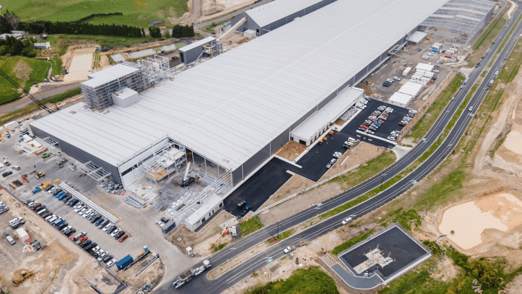
Basalt plasterboard plant
Revit rebar model for the kettle walls, slabs and foundations of a 67,000 m² GIB plasterboard plant.
View drawing samples (PDF)We prepare reinforcement shop drawings, bending schedules and 3D bar models for reinforcing suppliers, builders and structural engineers on both sides of the Tasman. Whether it is a house slab or a bridge pier, the engineer's design comes back as bars your shop can process and your fixers can place.
| Mark | Bar | Shape | No. | Length (mm) |
|---|---|---|---|---|
| B01 | N16 | 24 | 2450 | |
| B02 | N12 | 96 | 1380 | |
| B03 | N20 | 18 | 3100 | |
| B04 | N24 | 40 | 6000 | |
| B05 | N16 | 12 | 4200 |
Reinforcement detailing delivered for






Send us the structural drawings. We return checked drawings and schedules your shop can cut and bend from and your fixers can place from.
| Item | Scope |
|---|---|
| Rebar shop drawings | Placing drawings for every element with bar marks, covers, laps, spacing and section details. |
| Bar bending schedules | Schedules in your fabricator's format and shape codes, with bar masses by element and by pour. |
| 3D rebar models | Reinforcement modelled in Revit or Tekla for congested areas, clash checks and coordination with embeds and post-tensioning. |
| Placing drawings by pour | Drawings split to match the pour sequence, so fixers place one pour at a time and inspectors can check it against one sheet. |
| Estimation and take-offs | Reinforcement tonnages and bar lists from tender drawings for pricing and procurement. |
| Clash detection and coordination | Bars checked against cast-ins, ducts, anchors and other trades before anything is bent. |
| RFIs and revisions | Questions for the engineer logged as soon as we find them and answered before fabrication, with every revision clouded and the schedules reissued. |
| As-built records | Final drawings and schedules marked up to match what was actually poured, ready for your handover file. |
A footing or a bridge pier, every package follows this order.
Structural drawings, the specification and the engineer's reinforcement details, with design queries listed up front.
Covers, lap lengths, spacing and bend diameters confirmed for the job.
Pour breaks and construction joints agreed, so drawings and schedules follow the build sequence.
Reinforcement drawn in 2D or modelled in 3D, element by element.
Bar bending schedules produced from the drawings or model, with marks and masses that match.
Laps, intersections and cast-ins checked for buildability before issue.
Questions closed out with the engineer, revisions issued and logged.
Drawings and schedules released for fabrication, with as-built mark-ups once the pours are done.
Bridges, industrial plants, wastewater shafts, campuses and housing. Open any project sheet for a sample of our drawings and bending schedules.
Revit rebar model for the kettle walls, slabs and foundations of a 67,000 m² GIB plasterboard plant.
View drawing samples (PDF)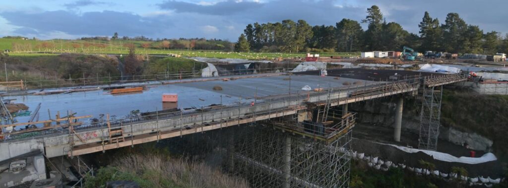
Rebar modelling and bar bending schedules in Revit for a four-lane bridge over the Waikato River, with clash detection and coordination.
View drawing samples (PDF)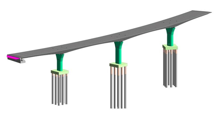
Revit rebar model for the piers, deck and abutments of a 300 m long, four-span balanced cantilever bridge over the Manawatū River.
View drawing samples (PDF)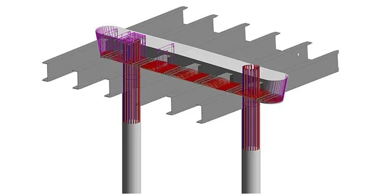
3D model of the concrete pierhead with bar bending schedules, clash detection and coordination with the client team.
View drawing samples (PDF)
Detailing of the post-tensioned beams for the airport extension.
View drawing samples (PDF)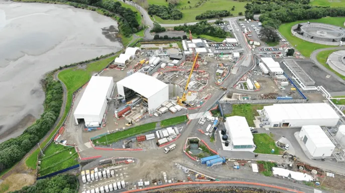
3D modelling and detailing of the chamber shafts and the supports carrying the pipework at Auckland’s main wastewater treatment plant.
View drawing samples (PDF)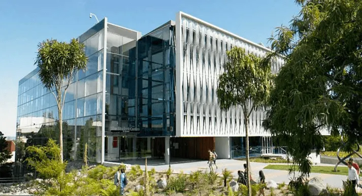
Rebar modelling and detailing for foundations, reinforced concrete walls and columns at the Hillcrest campus.
View drawing samples (PDF)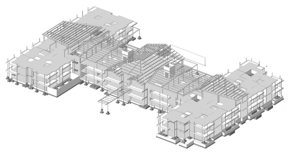
Rebar detailing for foundations, columns, beams and slabs, plus bending schedules issued to site.
View drawing samples (PDF)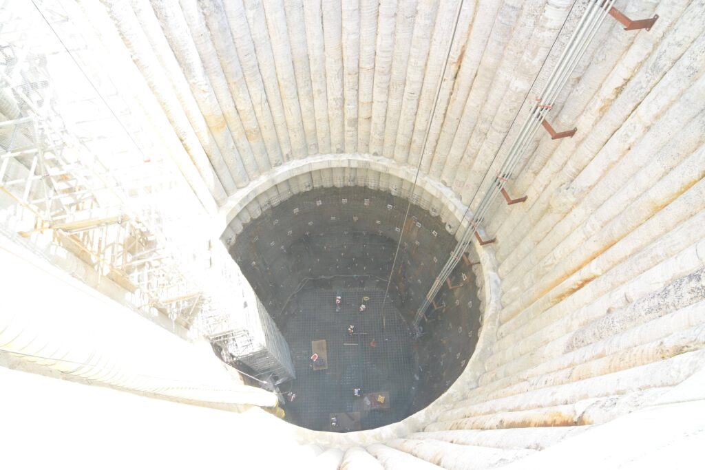
Rebar shop drawings and bar bending schedule for the permanent shaft lining lift.
View drawing samples (PDF)We detail for reinforcing suppliers as much as for contractors, so schedules arrive in the format, shape codes and bar marking your processing team expects.
Congested pierheads, transfer zones and shafts are modelled in Revit or Tekla, so clashes are found on screen instead of on the deck.
Bridge piers and decks, industrial plants, wastewater shafts, university buildings and aged care, across Australia and New Zealand.
When the reinforcement sits inside precast units, our precast detailing team coordinates the panel drawings with your bar schedules from day one.
Not covered here? Ring us on +61 431 334 750.
The structural drawings and specification, any reinforcement details from the engineer, the pour breaks if they are known, and your fabricator's shape codes and schedule format.
Yes. We supply schedules in Excel or CSV and set them up with your shape codes, bar marks and layout. Tell us what your processing software needs and we will confirm it before we start.
Most elements are detailed in 2D. We recommend 3D for congested or complex areas such as pierheads, transfer beams and shafts, or where the project needs model-based coordination.
Once we have looked over the drawings, you get a price and a delivery programme. On larger jobs the price can be broken down by pour or by stage.
Yes, regularly. Most of the projects on this page were detailed for New Zealand reinforcers and contractors, to NZS 3101.
Give us a few details and a link to the structural drawings. If anything is unclear we will ask, then come back with a price and a programme.
Big drawing sets travel best as a Dropbox, OneDrive or WeTransfer link. You can also email files to panchal@siliconc.com.au with the project name in the subject line.